


শিল্প সংবাদ

আরএফ সংযোগকারী কেনার সময় বিবেচনা করার জন্য শীর্ষ 10টি বিষয়
 2026.07.16
 শিল্প সংবাদ
ভূমিকা: RF সংযোগকারী নির্বাচনের সমালোচনামূলক সিদ্ধান্ত
ডান নির্বাচন আরএফ সমাক্ষ সংযোগকারী যেকোন উচ্চ-ফ্রিকোয়েন্সি সিস্টেম ডিজাইনের সবচেয়ে ফলপ্রসূ সিদ্ধান্তগুলির মধ্যে একটি। আপনি যে সংযোগকারীটি চয়ন করেন তা সরাসরি সংকেত অখণ্ডতা, সিস্টেম নির্ভরযোগ্যতা এবং দীর্ঘমেয়াদী অপারেশনাল খরচকে প্রভাবিত করে। টেলিযোগাযোগ, সম্প্রচার, মহাকাশ, এবং চিকিৎসা সরঞ্জাম জুড়ে হাজার হাজার অ্যাপ্লিকেশন মূল্যায়ন করার পরে, পরিষ্কার উপসংহার হল: সর্বোত্তম RF সংযোগকারী প্রতিবন্ধকতা, ফ্রিকোয়েন্সি, শক্তি, পরিবেশ এবং যান্ত্রিক স্থায়িত্বের মধ্যে একটি ভারসাম্যপূর্ণ ট্রেড-অফ দ্বারা নির্ধারিত হয়।
এই গাইড উপস্থাপন করে শীর্ষ 10 কারণ যে প্রকৌশল পেশাদার এবং সংগ্রহ বিশেষজ্ঞদের সোর্সিং যখন মূল্যায়ন করা আবশ্যক আরএফ সমাক্ষ সংযোগকারী . আপনি একজন ডিজাইন ইঞ্জিনিয়ার হোক না কেন, ক আরএফ সংযোগকারী সরবরাহকারী , অথবা একজন প্রকিউরমেন্ট ম্যানেজার এর সাথে কাজ করছেন কাস্টম আরএফ সংযোগকারী প্রস্তুতকারক , এই মানদণ্ড আপনাকে ডেটা-চালিত সিদ্ধান্ত নিতে সাহায্য করবে। আমরা শিল্প তথ্য, ক্ষেত্রের কর্মক্ষমতা রেকর্ড, এবং নেতৃস্থানীয়দের থেকে উত্পাদন সেরা অনুশীলনের উপর আঁকা আরএফ সংযোগকারী প্রস্তুতকারক 30 বছরেরও বেশি অভিজ্ঞতা সহ সুবিধা।
নিংবো হ্যানসন কমিউনিকেশন টেকনোলজি কোং লিমিটেড, একটি চীন ভিত্তিক আরএফ কোঅক্সিয়াল সংযোগকারী প্রস্তুতকারক এবং পাইকারি 50 ওহম এবং 75 ওহম আরএফ কোঅক্সিয়াল সংযোগকারী কারখানা , বিশ্বব্যাপী ক্লায়েন্টদের লক্ষ লক্ষ সংযোগকারী সরবরাহ করেছে। তাদের উল্লম্বভাবে সমন্বিত ক্রিয়াকলাপ - স্প্যানিং মেশিনিং, ইলেক্ট্রোপ্লেটিং এবং সমাবেশ - গুণমান এবং কাস্টমাইজেশনের জন্য একটি মানদণ্ড অফার করে। এই নিবন্ধটি আপনাকে একটি বিস্তৃত ক্রয় কাঠামো দিতে বিস্তৃত শিল্প মানগুলির সাথে তাদের প্রকৌশল অন্তর্দৃষ্টিগুলিকে সংশ্লেষ করে।
ফ্যাক্টর 1: ইম্পিডেন্স ম্যাচিং – 50 ওহম বনাম 75 ওহম
প্রতিবন্ধকতা হল আরএফ সংযোগকারীর কর্মক্ষমতার ভিত্তি। দুটি প্রভাবশালী মান হয় 50 ওহম আরএফ সমাক্ষ সংযোগকারী এবং 75 ওহম আরএফ সমাক্ষ সংযোগকারী . তাদের মধ্যে নির্বাচন নির্বিচারে নয়; এটি আপনার অ্যাপ্লিকেশনের শক্তি এবং সংকেত ক্ষতির প্রয়োজনীয়তা দ্বারা নির্ধারিত হয়।
A 50 ওহম আরএফ সমাক্ষ সংযোগকারী পাওয়ার হ্যান্ডলিং এবং কম ক্ষতির জন্য অপ্টিমাইজ করা হয়েছে, এটি বেশিরভাগ যোগাযোগ ব্যবস্থা, পরীক্ষার সরঞ্জাম এবং বেস স্টেশনগুলির জন্য আদর্শ করে তুলেছে। বিপরীতে, ক 75 ওহম আরএফ সমাক্ষ সংযোগকারী দীর্ঘ তারের রানের উপর টেনশন কম করে, যে কারণে এটি ভিডিও, সম্প্রচার এবং কেবল টেলিভিশন অবকাঠামোতে প্রাধান্য পায়।
শিল্প তথ্য অনুযায়ী, একটি 50-ওহম সিস্টেম প্রায় পরিচালনা করতে পারে 2.5 গুণ বেশি শক্তি একই ভোল্টেজ স্ট্যান্ডিং ওয়েভ রেশিও (VSWR) এ 75-ওহম সিস্টেমের চেয়ে। বিপরীতভাবে, 75-ওহম সমাক্ষ তারগুলি প্রায় প্রদর্শন করে 15% কম টেনশন 50-ওহম তারের তুলনায় 1 GHz এ প্রতি 100 মিটার। এই পার্থক্যগুলি দীর্ঘ-দূরত্বের সংক্রমণে উল্লেখযোগ্য।
কেনার সময়, সর্বদা প্রতিবন্ধকতা রেটিং যাচাই করুন। একটি 75-ওহম তারের সাথে একটি 50-ওহম সংযোগকারীর মিল না হলে (বা বিপরীতভাবে) প্রায় 1.5:1 এর একটি VSWR প্রবর্তন করে, যার ফলে 4% থেকে 8% সংকেত প্রতিফলন এবং increasing insertion loss by 0.2–0.5 dB per connection. Over multiple connections, this degrades system performance dramatically.
মূল গ্রহণ: ব্যবহার করুন 50 ওহম আরএফ সমাক্ষ সংযোগকারীs উচ্চ-শক্তি, কম-ক্ষতির সিস্টেমের জন্য (ওয়্যারলেস, রাডার, পরীক্ষা)। ব্যবহার করুন 75 ওহম আরএফ সমাক্ষ সংযোগকারীs ভিডিও, সম্প্রচার, এবং CATV-এর জন্য যেখানে দূরত্বের উপর সংকেত ক্ষয় করা প্রাথমিক উদ্বেগের বিষয়।
ফ্যাক্টর 2: অপারেটিং ফ্রিকোয়েন্সি রেঞ্জ
একটি এর ফ্রিকোয়েন্সি পরিসীমা আরএফ সমাক্ষ সংযোগকারী এর ব্যবহারযোগ্যতার উপরের সীমা নির্ধারণ করে। এই সীমা অতিক্রম করার ফলে উচ্চ-ক্রম প্রচার মোড, বৃদ্ধি VSWR, এবং অগ্রহণযোগ্য সন্নিবেশ ক্ষতি হয়। আধুনিক 5G, মহাকাশ, এবং উচ্চ-গতির ডেটা অ্যাপ্লিকেশনগুলির জন্য, ফ্রিকোয়েন্সি রেটিংগুলি আলোচনার যোগ্য নয়৷
বিভিন্ন সংযোগকারী প্রকার বিভিন্ন ফ্রিকোয়েন্সি ব্যান্ড সমর্থন করে। উদাহরণস্বরূপ, স্ট্যান্ডার্ড এসএমএ সংযোগকারীগুলি পর্যন্ত পরিচালনা করে 18 GHz , প্রসারিত নির্ভুল সংস্করণ সহ 26.5 GHz . এন-টাইপ সংযোগকারী সাধারণত পর্যন্ত কাজ করে 11 GHz স্ট্যান্ডার্ড সংস্করণের জন্য এবং 18 GHz নির্ভুলতা বৈকল্পিক জন্য. বিএনসি সংযোগকারী সীমাবদ্ধ 4 GHz , এগুলিকে ভিডিও এবং নিম্ন-ফ্রিকোয়েন্সি অ্যাপ্লিকেশনের জন্য উপযুক্ত করে তোলে।
নির্বাচন করার সময় ক উচ্চ ফ্রিকোয়েন্সি আরএফ সমাক্ষ সংযোগকারী , সর্বদা প্রস্তুতকারকের নির্দিষ্ট ফ্রিকোয়েন্সি পরিসীমা পরীক্ষা করুন। mmWave অ্যাপ্লিকেশনের জন্য (30 GHz এর উপরে), 2.92 mm (40 GHz), 2.4 mm (50 GHz), এবং 1.85 mm (67 GHz) এর মতো সংযোগকারী পাওয়া যায়। এগুলি প্রায়ই একটি দ্বারা কাস্টম-ইঞ্জিনিয়ার করা হয় কাস্টম আরএফ সমাক্ষ সংযোগকারী প্রস্তুতকারক কঠোর প্রয়োজনীয়তা পূরণ করতে।
শিল্প পরীক্ষার ডেটা দেখায় যে একটি সংযোগকারীকে তার সর্বাধিক রেটযুক্ত ফ্রিকোয়েন্সির 80% এ পরিচালনা করলে সর্বোত্তম কর্মক্ষমতা পাওয়া যায় 1.15:1 এর নিচে VSWR এবং insertion loss under 0.15 dB. Pushing beyond 90% of the rated frequency can increase VSWR to 1.3:1 and double insertion loss. Therefore, always select a connector with a frequency margin of at least 20% আপনার সিস্টেমের অপারেটিং ফ্রিকোয়েন্সির উপরে।
ফ্যাক্টর 3: পাওয়ার হ্যান্ডলিং ক্ষমতা
পাওয়ার হ্যান্ডলিং হল সর্বাধিক আরএফ পাওয়ার যা একটি সংযোগকারী অতিরিক্ত গরম বা আর্কিং ছাড়াই প্রেরণ করতে পারে। এই ফ্যাক্টরটি ব্রডকাস্ট ট্রান্সমিটার, রাডার সিস্টেম এবং হাই-পাওয়ার টেস্ট সেটআপে গুরুত্বপূর্ণ। পাওয়ার হ্যান্ডলিং সংযোগকারীর উপকরণ, অস্তরক শক্তি এবং তাপ অপচয়ের উপর নির্ভর করে।
ক জন্য 50 ওহম আরএফ সমাক্ষ সংযোগকারী , সাধারণ পাওয়ার রেটিং 1 GHz রেঞ্জ থেকে 50 ওয়াট থেকে 500 ওয়াট সংযোগকারী আকার এবং নকশা উপর নির্ভর করে। উদাহরণস্বরূপ, একটি এন-টাইপ সংযোগকারী পর্যন্ত পরিচালনা করতে পারে 300 W 1 GHz এ, যখন একটি SMA সংযোগকারীকে সাধারণত রেট দেওয়া হয় 50 ওয়াট একই ফ্রিকোয়েন্সিতে। উচ্চ ফ্রিকোয়েন্সিতে, স্কিন ইফেক্ট এবং ডাইইলেকট্রিক হিটিং এর কারণে পাওয়ার হ্যান্ডলিং কমে যায়।
সংযোগকারী নির্মাতাদের থার্মাল মডেলিং ডেটা অনুসারে, একটি সংযোগকারীর পাওয়ার রেটিং প্রায় কমে যায় 40% যখন ফ্রিকোয়েন্সি দ্বিগুণ হয় 1 GHz থেকে 2 GHz, এবং অন্য একটি দ্বারা 30% 2 GHz থেকে 4 GHz এর মানে হল 1 GHz এ 100 W এর জন্য রেট করা একটি সংযোগকারী 4 GHz এ শুধুমাত্র 42 W হ্যান্ডেল করতে পারে। একটি থেকে সোর্সিং যখন আরএফ সংযোগকারী OEM সরবরাহকারী , সর্বদা আপনার অপারেটিং ফ্রিকোয়েন্সির জন্য নির্দিষ্ট পাওয়ার ডিরেটিং কার্ভের অনুরোধ করুন।
উচ্চ-শক্তি অ্যাপ্লিকেশনের জন্য, সঙ্গে সংযোগকারী বিবেচনা করুন টেফলন বা পিটিএফই অস্তরক এবং রূপালী ধাতুপট্টাবৃত পরিচিতি , যা উচ্চতর তাপ পরিবাহিতা প্রদান করে। ক শিল্প RF সংযোগকারী সরবরাহকারী বর্ধিত তাপ সিঙ্ক বা চরম শক্তি স্তরের জন্য জোরপূর্বক-এয়ার কুলিং বিকল্প সহ কাস্টম সমাধান প্রদান করতে পারে।
ফ্যাক্টর 4: পরিবেশগত স্থায়িত্ব
RF সংযোগকারীগুলি প্রায়শই কঠোর পরিবেশে মোতায়েন করা হয় - আউটডোর বেস স্টেশন, মহাকাশ কেবিন, শিল্প ফ্লোর এবং সামুদ্রিক জাহাজ। পরিবেশগত কারণগুলির মধ্যে রয়েছে তাপমাত্রার চরমতা, আর্দ্রতা, লবণের স্প্রে, ধুলো এবং কম্পন। ক্ষেত্রটিতে ব্যর্থ হওয়া একটি সংযোগকারীর ডাউনটাইম এবং প্রতিস্থাপনের জন্য হাজার হাজার ডলার খরচ হতে পারে।
কী পরিবেশগত স্পেসিফিকেশনের জন্য সন্ধান করতে হবে অপারেটিং তাপমাত্রা পরিসীমা , আইপি রেটিং (প্রবেশ সুরক্ষা), এবং লবণ স্প্রে প্রতিরোধের (MIL-STD-810)। বহিরঙ্গন অ্যাপ্লিকেশনের জন্য, একটি IP67 বা IP68 রেটিং সহ সংযোগকারীগুলি সুপারিশ করা হয়৷ এগুলি সম্পূর্ণ ধুলো সুরক্ষা প্রদান করে এবং 30 মিনিটের জন্য 1 মিটার পর্যন্ত জলে নিমজ্জন সহ্য করতে পারে।
ক্ষেত্র ব্যর্থতা বিশ্লেষণ থেকে তথ্য যে দেখায় 60% এর বেশি বহিরঙ্গন টেলিকম সাইটে সংযোগকারী ব্যর্থতা আর্দ্রতা প্রবেশ এবং ক্ষয় দ্বারা সৃষ্ট হয়. সঙ্গে সংযোগকারী ব্যবহার করে সোনার ধাতুপট্টাবৃত পরিচিতি এবং স্টেইনলেস স্টীল বা পিতলের দেহ সঙ্গে জারা-প্রতিরোধী কলাই দ্বারা সেবা জীবন প্রসারিত করতে পারেন 3 থেকে 5 বার স্ট্যান্ডার্ড নিকেল-ধাতুপট্টাবৃত সংযোগকারী তুলনায়.
A আরএফ সংযোগকারী প্রস্তুতকারক নিংবো হ্যানসনের মতো ইন-হাউস ইলেক্ট্রোপ্লেটিং ক্ষমতা সহ, আপনার পরিবেশগত প্রয়োজনীয়তার সাথে মেলে - স্বর্ণ, রূপা, নিকেল বা টিন - কাস্টমাইজড প্লেটিং বিকল্পগুলি অফার করতে পারে৷ মহাকাশ অ্যাপ্লিকেশনের জন্য, সংযোগকারী অবশ্যই পূরণ করতে হবে MIL-PRF-39012 বা নাসা আউটগ্যাসিং মান, যা সাধারণত প্রয়োজন -65°C থেকে 165°C অপারেটিং পরিসীমা এবং 100% তাপ সাইক্লিং পরীক্ষা।
ফ্যাক্টর 5: যান্ত্রিক চক্র জীবন (সঙ্গম স্থায়িত্ব)
যান্ত্রিক চক্র জীবন একটি সংযোগকারী তার বৈদ্যুতিক বা যান্ত্রিক কর্মক্ষমতা অবনতির আগে সহ্য করতে পারে এমন সঙ্গম এবং অসংলগ্ন ক্রিয়াকলাপগুলির সংখ্যাকে বোঝায়। এটি পরীক্ষার সরঞ্জাম, হ্যান্ডহেল্ড ডিভাইস এবং যেকোন অ্যাপ্লিকেশনের জন্য একটি গুরুত্বপূর্ণ কারণ যেখানে সংযোগকারীগুলি ঘন ঘন সংযুক্ত এবং সংযোগ বিচ্ছিন্ন হয়।
বাণিজ্যিক-গ্রেড সংযোগকারীরা সাধারণত অফার করে 500 থেকে 1,000 সঙ্গম চক্র . নির্ভুলতা বা সামরিক-গ্রেড সংযোগকারী অতিক্রম করতে পারে 2,000 চক্র . সীমাবদ্ধ কারণগুলি হল যোগাযোগ পরিধান, কলাইয়ের অবক্ষয় এবং অস্তরক সংকোচন। স্বর্ণের প্রলেপ, এর ঘর্ষণ সহগ কম, উচ্চ-চক্র প্রয়োগের জন্য পছন্দ করা হয়।
ফিল্ড ডেটা নির্দেশ করে যে 1,000 চক্রের পরে, একটি আদর্শ SMA সংযোগকারী একটি দেখাতে পারে 0.1 ডিবি বৃদ্ধি সন্নিবেশ ক্ষতি এবং একটি 0.05 বৃদ্ধি VSWR এ। বিপরীতে, পুরু সোনার প্রলেপ (≥ 1.27 µm) সহ একটি উচ্চ-স্থায়িত্ব সংযোগকারীর জন্য স্থিতিশীল কর্মক্ষমতা বজায় রাখতে পারে 2,500 চক্র ন্যূনতম অবক্ষয় সহ।
থেকে ক্রয় করার সময় ক পাইকারি আরএফ সংযোগকারী সরবরাহকারী, সর্বদা নির্দিষ্ট চক্রের জীবন সম্পর্কে জিজ্ঞাসা করুন। অটোমেটেড টেস্ট ইকুইপমেন্ট (ATE) এর জন্য যেখানে প্রতি বছর কানেক্টর হাজার হাজার বার মেট করা যেতে পারে, এর জন্য রেট করা কানেক্টর বেছে নিন 5,000 চক্র বা more. Some কাস্টম আরএফ সংযোগকারী প্রস্তুতকারক অর্জনের জন্য বেরিলিয়াম কপার পরিচিতি এবং অতিরিক্ত-পুরু কলাই দিয়ে চাঙ্গা নকশা অফার করে 10,000-চক্র স্থায়িত্ব
ফ্যাক্টর 6: তারের সামঞ্জস্যতা এবং সমাপ্তি
সংযোগকারীটি অবশ্যই তারের প্রকারের সাথে সামঞ্জস্যপূর্ণ হতে হবে যেটি আপনি ব্যবহার করতে চান—সেটি সেমি-রিজিড, নমনীয় বা ঢেউতোলা হোক। সমাপ্তি পদ্ধতি (সোল্ডার, ক্রিম্প, ক্ল্যাম্প বা পুশ-অন) এছাড়াও ইনস্টলেশনের সহজতা এবং দীর্ঘমেয়াদী নির্ভরযোগ্যতাকে প্রভাবিত করে। এখানে একটি অমিল খারাপ বৈদ্যুতিক কর্মক্ষমতা এবং যান্ত্রিক ব্যর্থতা হতে পারে.
সাধারণ তারের ইন্টারফেস অন্তর্ভুক্ত RG-58, RG-59, RG-213, LMR-400, এবং 1/2" হেলিয়াক্স . প্রতিটির নির্দিষ্ট বাইরের ব্যাস, অস্তরক ব্যাস, এবং প্রতিবন্ধক বৈশিষ্ট্য রয়েছে। ক 50 ওহম আরএফ সমাক্ষ সংযোগকারী RG-58 (5 mm OD) এর জন্য ডিজাইন করা অ্যাডাপ্টার ছাড়া RG-213 (10.3 mm OD) ফিট হবে না৷
ইনস্টলেশন রিপোর্ট থেকে তথ্য যে দেখায় 30% এর বেশি ক্ষেত্রের পারফরম্যান্সের সমস্যাগুলি অনুপযুক্ত তারের সমাপ্তি থেকে উদ্ভূত হয়—হয় ভুল ক্রিম্প চাপ, অপর্যাপ্ত সোল্ডার, অথবা কেন্দ্রের পিনগুলি ভুলভাবে সংযুক্ত করা। সঙ্গে সংযোগকারী ব্যবহার করে সোল্ডার-মুক্ত ক্রিম্প বা কম্প্রেশন সমাপ্তি পর্যন্ত দ্বারা ইনস্টলেশন ত্রুটি কমাতে পারে 70% .
কাস্টম সমাবেশের জন্য, ক কাস্টম আরএফ সমাক্ষ সংযোগকারী প্রস্তুতকারক নিখুঁত প্রতিবন্ধকতা ম্যাচিং এবং যান্ত্রিক ফিট নিশ্চিত করে আপনার তারের প্রকারের জন্য বিশেষভাবে একটি সংযোগকারী ডিজাইন করতে পারে। অনেক আরএফ সংযোগকারী OEM সরবরাহকারী ক্যাবল অ্যাসেম্বলি পরিষেবা প্রদান করে, ফ্যাক্টরি-পরীক্ষিত পারফরম্যান্স সহ প্রি-টার্মিনেটেড ক্যাবল সরবরাহ করে, যা ফিল্ড টারমিনেশন পরিবর্তনশীলতা দূর করে।
ফ্যাক্টর 7: উপাদান এবং কলাই গুণমান
একটি ব্যবহৃত উপকরণ আরএফ সমাক্ষ সংযোগকারী সরাসরি এর বৈদ্যুতিক পরিবাহিতা, জারা প্রতিরোধের, এবং যান্ত্রিক শক্তিকে প্রভাবিত করে। দেহ সাধারণত পিতল, স্টেইনলেস স্টিল বা অ্যালুমিনিয়াম দিয়ে তৈরি। কেন্দ্রের যোগাযোগ প্রায়শই বেরিলিয়াম তামা বা ফসফর ব্রোঞ্জ, সোনা, রৌপ্য বা নিকেল দিয়ে প্রলেপ দেওয়া হয়।
গোল্ড প্লেটিং হল উচ্চ-কার্যকারিতা সংযোগকারীর জন্য স্বর্ণের মান (শ্লেষের উদ্দেশ্যে) এর চমৎকার পরিবাহিতা, জারা প্রতিরোধের, এবং কম যোগাযোগ প্রতিরোধের কারণে। একটি সোনার প্রলেপ বেধ 0.5 থেকে 1.27 µm বাণিজ্যিক সংযোগকারীর জন্য সাধারণ, যখন সামরিক এবং মহাকাশ গ্রেড প্রয়োজন 1.27 থেকে 2.5 µm একটি নিকেল আন্ডারপ্লেটের উপরে সোনার।
সিলভার প্লেটিং সর্বোচ্চ পরিবাহিতা প্রদান করে কিন্তু সময়ের সাথে সাথে কলঙ্কিত হয়, যোগাযোগের প্রতিরোধ ক্ষমতা বাড়ায়। নিকেল প্রলেপ টেকসই এবং খরচ-কার্যকর কিন্তু সোনা বা রৌপ্যের তুলনায় এর প্রতিরোধ ক্ষমতা বেশি। ত্বরিত বার্ধক্য পরীক্ষার ডেটা দেখায় যে সোনার ধাতুপট্টাবৃত সংযোগকারীগুলি বজায় রাখে 2 mΩ এর কম 1,000 চক্রের পরে যোগাযোগের প্রতিরোধ, যখন নিকেল-ধাতুপট্টাবৃত সংযোগকারীগুলি অতিক্রম করতে পারে 10 mΩ একই সংখ্যক চক্রের পরে।
একটি সম্মানজনক আরএফ সংযোগকারী সরবরাহকারী বিস্তারিত কলাই স্পেসিফিকেশন এবং পরীক্ষার রিপোর্ট প্রদান করবে। সমালোচনামূলক অ্যাপ্লিকেশনের জন্য, সঙ্গে সরবরাহকারী বিবেচনা করুন ISO 9001 প্রত্যয়িত ইলেক্ট্রোপ্লেটিং প্রক্রিয়া, যেমন নিংবো হ্যানসন, যা কঠোর মান নিয়ন্ত্রণ নিশ্চিত করতে নিজস্ব ইলেক্ট্রোপ্লেটিং ওয়ার্কশপ পরিচালনা করে।
ফ্যাক্টর 8: আকার এবং মাউন্ট কনফিগারেশন
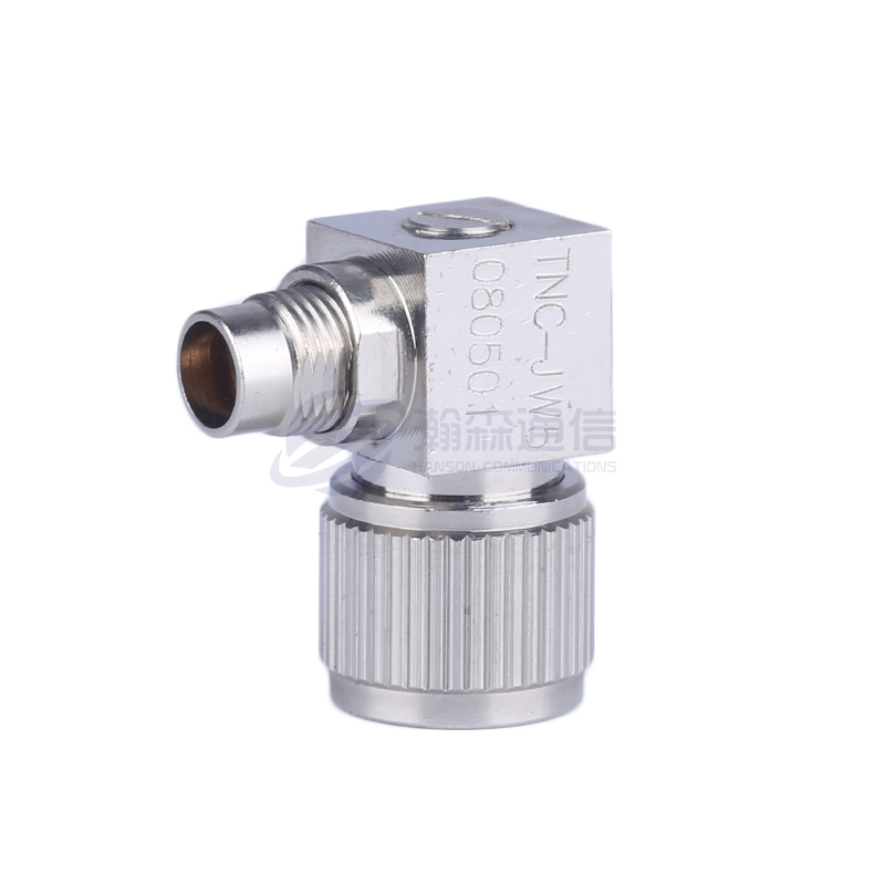
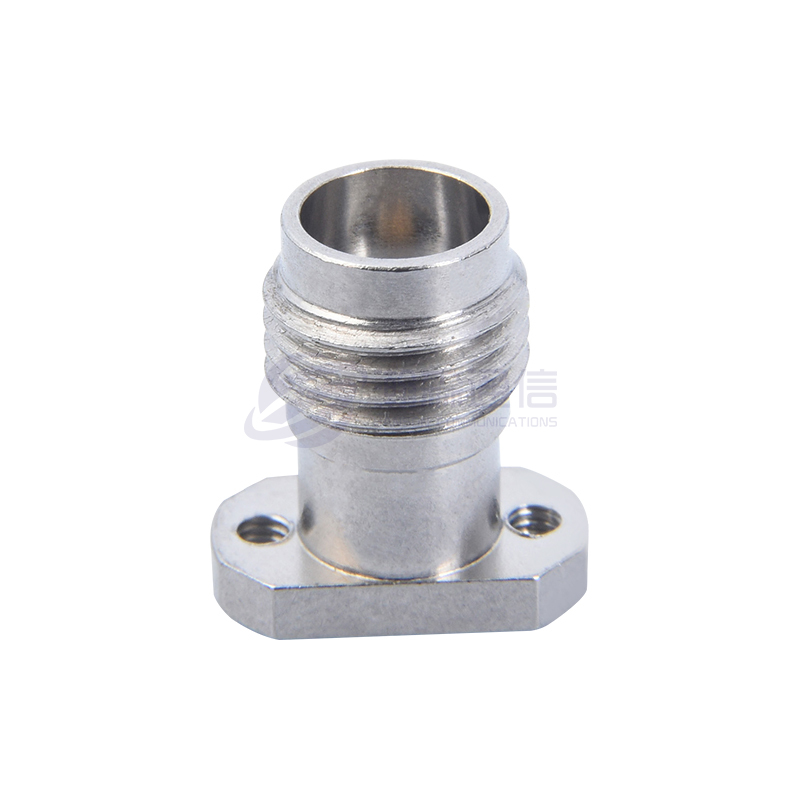
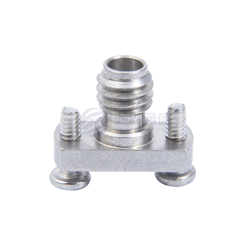
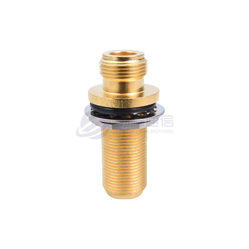
শারীরিক আকার এবং মাউন্টিং শৈলী প্রায়শই উপেক্ষা করা হয় তবে PCB ডিজাইন, প্যানেল বিন্যাস এবং স্থান-সীমাবদ্ধ ঘেরের জন্য গুরুত্বপূর্ণ। সংযোগকারী বিভিন্ন ফর্ম কারণের মধ্যে আসে: বাল্কহেড, ফ্ল্যাঞ্জ, প্রান্ত-মাউন্ট, ডান-কোণ এবং সোজা . মাউন্টিং কনফিগারেশন আপনার যান্ত্রিক নকশা এবং সমাবেশ প্রক্রিয়ার সাথে সারিবদ্ধ হওয়া আবশ্যক।
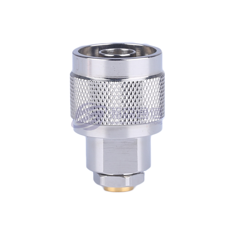
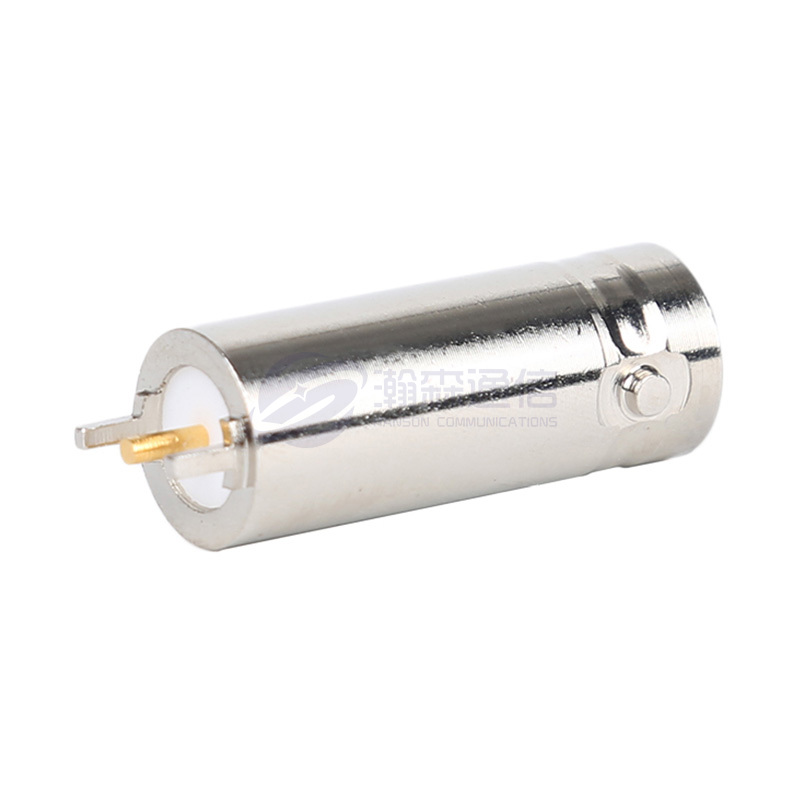
উদাহরণস্বরূপ, SMA সংযোগকারীগুলি কমপ্যাক্ট (থ্রেডেড 1/4-36 UNF) এবং ঘন PCB লেআউটের জন্য আদর্শ, যখন N-টাইপ সংযোগকারীগুলি বড় (5/8-24 UNEF) এবং উচ্চ শক্তি প্রয়োগের জন্য উপযুক্ত। BNC সংযোগকারীগুলিতে দ্রুত সংযোগের জন্য একটি বেয়নেট-স্টাইলের কাপলিং বৈশিষ্ট্য রয়েছে, যা পরীক্ষা এবং পরিমাপে জনপ্রিয়।
প্যানেল-মাউন্ট করা সংযোগকারীদের সুনির্দিষ্ট কাটআউট এবং ফ্ল্যাঞ্জের মাত্রা প্রয়োজন। সমাবেশ লাইন থেকে ডেটা নির্দেশ করে যে সংযোগকারী ব্যবহার করে প্রমিত মাউন্ট মাত্রা দ্বারা উৎপাদন সময় কমিয়ে দেয় 15% কাস্টম মাউন্ট ডিজাইনের তুলনায়। একটি সঙ্গে কাজ করার সময় কাস্টম আরএফ সংযোগকারী প্রস্তুতকারক , আপনি অনন্য যান্ত্রিক সীমাবদ্ধতা পূরণের জন্য কাস্টম ফ্ল্যাঞ্জ প্যাটার্ন, থ্রেডের আকার বা পিনের দৈর্ঘ্যের অনুরোধ করতে পারেন।
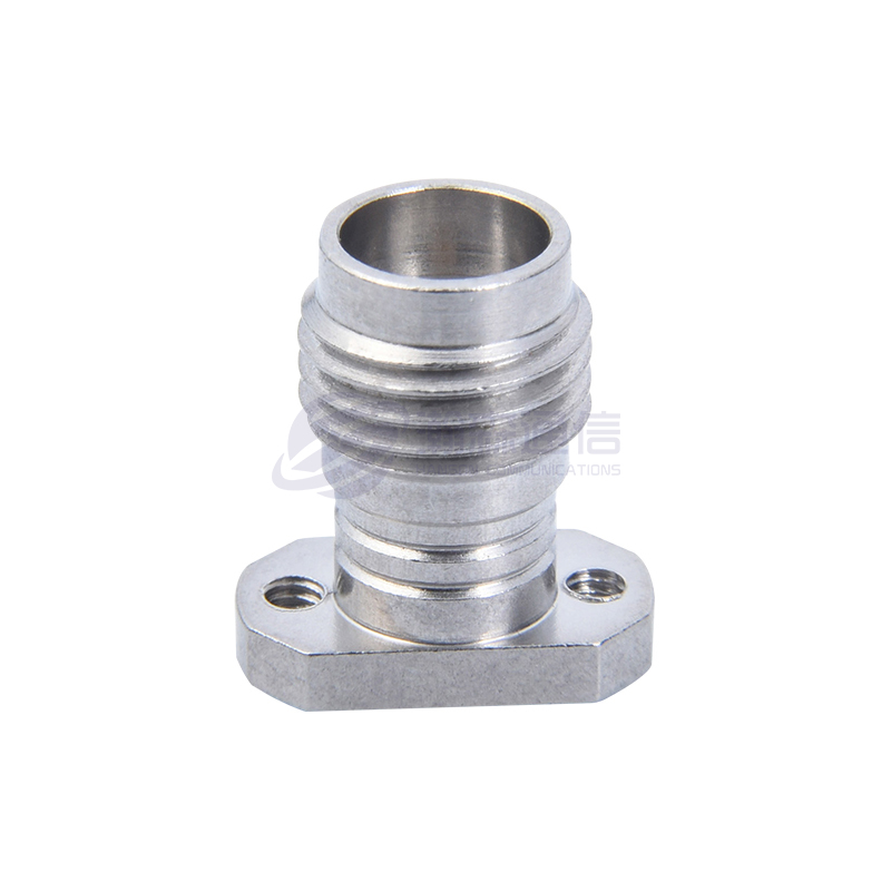
উচ্চ-ঘনত্বের অ্যাপ্লিকেশনের জন্য, যেমন ক্ষুদ্র সংযোজক বিবেচনা করুন এসএমপি বা এসএসএমপি , যা অফার 40% স্ট্যান্ডার্ড SMA সংযোগকারীর চেয়ে ছোট পায়ের ছাপ। এগুলি সাধারণত মাল্টি-চ্যানেল সিস্টেম এবং ফেজড-অ্যারে অ্যান্টেনায় ব্যবহৃত হয়। ক আরএফ সংযোগকারী OEM সরবরাহকারী আপনার বিদ্যমান লেআউটে এগুলিকে একীভূত করতে ডিজাইন সমর্থন প্রদান করতে পারে।
ফ্যাক্টর 9: বৈদ্যুতিক কর্মক্ষমতা মেট্রিক্স
প্রতিবন্ধকতা এবং কম্পাঙ্কের বাইরে, বেশ কয়েকটি বৈদ্যুতিক পরামিতি সংযোগকারীর গুণমানকে সংজ্ঞায়িত করে: VSWR (ভোল্টেজ স্ট্যান্ডিং ওয়েভ অনুপাত) , সন্নিবেশ ক্ষতি , ফেরত ক্ষতি , এবং ফেজ স্থিতিশীলতা . এই মেট্রিকগুলি একটি সংযোগকারীর RF কার্যকারিতার প্রকৃত সূচক।
VSWR প্রতিবন্ধকতা অমিল পরিমাপ করে; নিম্ন ভাল. অধিকাংশ অ্যাপ্লিকেশনের জন্য, একটি VSWR 1.15:1 বা less is excellent, while 1.25:1 গ্রহণযোগ্য সন্নিবেশ ক্ষতি, dB তে পরিমাপ করা হয়, সংযোগকারীর মাধ্যমে সংকেত পাওয়ার ক্ষতির প্রতিনিধিত্ব করে। একটি ভাল সংযোগকারীর নীচে সন্নিবেশ ক্ষতি থাকা উচিত 0.2 ডিবি অপারেটিং ফ্রিকোয়েন্সিতে।
রিটার্ন লস হল VSWR এর পারস্পরিক সম্পর্ক; একটি ফেরত ক্ষতি 20 ডিবি 1.22:1 এর VSWR এর সাথে মিলে যায়। উচ্চ রিটার্ন ক্ষতি মানে ভাল প্রতিবন্ধকতা ম্যাচিং। পর্যায় স্থিতিশীলতা পর্যায়ক্রমিক-অ্যারে সিস্টেম এবং সুসংগত পরিমাপের ক্ষেত্রে গুরুত্বপূর্ণ; সঙ্গে সংযোগকারী PTFE বা কঠিন অস্তরক তাপমাত্রা পরিবর্তনের সাথে নিম্ন ফেজ ড্রিফ্ট প্রদর্শন করুন।
ক থেকে তুলনামূলক পরীক্ষা আরএফ সংযোগকারী প্রস্তুতকারক দেখান যে নির্ভুল সংযোগকারীরা অর্জন করে VSWR ≤ 1.10:1 এবং insertion loss ≤ 0.1 dB at 18 GHz, while standard commercial connectors typically have VSWR ≤ 1.25:1 and insertion loss ≤ 0.3 dB. When sourcing from a শিল্প RF সংযোগকারী সরবরাহকারী , কর্মক্ষমতা যাচাই করতে সর্বদা সম্পূর্ণ S-প্যারামিটার ডেটা (S11, S21) অনুরোধ করুন।
ফ্যাক্টর 10: সাপ্লাই চেইন এবং প্রস্তুতকারক নির্বাচন
চূড়ান্ত ফ্যাক্টর—এবং প্রায়শই সংগ্রহের জন্য সবচেয়ে গুরুত্বপূর্ণ—একটি নির্ভরযোগ্য নির্বাচন করা আরএফ সংযোগকারী সরবরাহকারী . সাপ্লাই চেইনের স্থায়িত্ব, মান নিয়ন্ত্রণ এবং কাস্টমাইজেশন ক্ষমতা সরাসরি আপনার প্রকল্পের টাইমলাইন এবং পণ্যের গুণমানকে প্রভাবিত করে। ক আরএফ সংযোগকারী প্রস্তুতকারক উল্লম্ব ইন্টিগ্রেশন সহ স্বতন্ত্র সুবিধা প্রদান করে।
নিংবো হ্যানসন কমিউনিকেশন টেকনোলজি কোং লিমিটেড একটি উল্লম্বভাবে সমন্বিত উদাহরণ দেয় কাস্টম আরএফ সংযোগকারী প্রস্তুতকারক . 30 বছরেরও বেশি অভিজ্ঞতার সাথে, তারা তাদের নিজস্ব মেশিনিং, ইলেক্ট্রোপ্লেটিং এবং সমাবেশ কর্মশালা পরিচালনা করে। এই নিয়ন্ত্রণটি সামঞ্জস্যপূর্ণ গুণমান, ছোট লিড টাইম এবং পরিচালনা করার ক্ষমতা নিশ্চিত করে কাস্টম আরএফ সংযোগকারী প্রস্তুতকারক অনুরোধ—বিশেষ প্লেটিং থেকে অনন্য যান্ত্রিক কনফিগারেশন পর্যন্ত।
মূল্যায়ন করার সময় a আরএফ সংযোগকারী OEM সরবরাহকারী , তাদের সার্টিফিকেশন, উৎপাদন ক্ষমতা, এবং গুণমান নিশ্চিতকরণ প্রক্রিয়া বিবেচনা করুন। ISO 9001 সার্টিফিকেশন মান ব্যবস্থাপনার প্রতি অঙ্গীকার নির্দেশ করে। অতিরিক্তভাবে, সরবরাহকারীদের সন্ধান করুন যারা অফার করে পাইকারি আরএফ সংযোগকারী নমনীয় MOQs (ন্যূনতম অর্ডার পরিমাণ) সহ প্রোটোটাইপিং এবং ব্যাপক উত্পাদন উভয় সমর্থন করার জন্য।
শিল্প সমীক্ষা থেকে তথ্য ইঙ্গিত যে ৪৫% এর বেশি সাপ্লাই চেইন বিলম্ব বা গুণমানের অসঙ্গতির কারণে RF কম্পোনেন্ট সংগ্রহের সমস্যা। অংশীদারিত্ব a আরএফ সমাক্ষ সংযোগকারী OEM supplier যে বজায় রাখে 95% অন-টাইম ডেলিভারি এবং 1% এর কম ত্রুটির হার উল্লেখযোগ্যভাবে প্রকল্পের ঝুঁকি কমাতে পারে। ভলিউম অর্ডার দেওয়ার আগে সর্বদা নমুনা এবং পরীক্ষার রিপোর্টের অনুরোধ করুন।
তুলনামূলক ডেটা বিশ্লেষণ
নিম্নলিখিত চার্টগুলি এর জন্য মূল কর্মক্ষমতা ডেটা কল্পনা করে৷ আরএফ সমাক্ষ সংযোগকারী , এক নজরে স্পেসিফিকেশন তুলনা করতে সাহায্য করে। সমস্ত ডেটা শিল্প-মান পরিমাপ এবং প্রস্তুতকারকের নির্দিষ্টকরণের উপর ভিত্তি করে।
সংযোগকারী প্রকার দ্বারা ফ্রিকোয়েন্সি পরিসীমা
সাধারণ আরএফ সংযোগকারী প্রকারের জন্য সর্বাধিক অপারেটিং ফ্রিকোয়েন্সি
সন্নিবেশ ক্ষতি বনাম ফ্রিকোয়েন্সি (সাধারণ)
সন্নিবেশ ক্ষতি ফ্রিকোয়েন্সি সঙ্গে বৃদ্ধি; 75-ওহম ডিজাইন সমতুল্য ফ্রিকোয়েন্সিতে কম ক্ষতি দেখায়
সংযোগকারী গ্রেড দ্বারা সঙ্গম চক্র জীবন
সংযোগকারী গ্রেড জুড়ে সাধারণ মিলন চক্র রেটিং
পারফরম্যান্স রাডার: 50 ওহম বনাম 75 ওহম সংযোগকারী
আপেক্ষিক কর্মক্ষমতা তুলনা: 50 ওহম বনাম 75 ওহম সংযোগকারী
শিল্পের স্পেসিফিকেশন এবং প্রস্তুতকারকের পরীক্ষার রিপোর্ট (2024-2026) থেকে সংকলিত চার্ট ডেটা।
প্রায়শই জিজ্ঞাসিত প্রশ্নাবলী
প্রশ্ন 1: কেন আরএফ সংযোগকারী প্রতিবন্ধকতা মিলে যায়?
প্রতিবন্ধকতা ম্যাচিং সংকেত প্রতিফলন প্রতিরোধ করে এবং সর্বোচ্চ শক্তি স্থানান্তর নিশ্চিত করে। অমিলের কারণে VSWR, সন্নিবেশের ক্ষতি বৃদ্ধি এবং সংকেত অখণ্ডতা হ্রাস পায়।
প্রশ্ন 2: কোন আরএফ সংযোগকারী সেরা?
এটি আবেদনের উপর নির্ভর করে। সাধারণ মাইক্রোওয়েভের জন্য SMA, ভিডিওর জন্য BNC এবং আউটডোর এবং হাই-পাওয়ার অ্যাপ্লিকেশনের জন্য N-টাইপ সেরা।
প্রশ্ন 3: SMA সংযোগকারীরা কোন ফ্রিকোয়েন্সি পরিচালনা করতে পারে?
স্ট্যান্ডার্ড SMA সংযোগকারী 18 GHz পর্যন্ত পরিচালনা করে, যথার্থ সংস্করণ 26.5 GHz পর্যন্ত পৌঁছায়।
প্রশ্ন 4: কেন 75 ওহমের পরিবর্তে 50 ওহম ব্যবহার করবেন?
50 ওহম পাওয়ার হ্যান্ডলিং এবং কম ক্ষতির জন্য অপ্টিমাইজ করা হয়, যখন 75 ওহম ভিডিও এবং সম্প্রচারে দীর্ঘ তারের জন্য ক্ষয় কমিয়ে দেয়।
প্রশ্ন 5: আরএফ সংযোগকারীগুলি কি বিনিময়যোগ্য?
সরাসরি না। বিভিন্ন ইন্টারফেস (SMA, BNC, N, ইত্যাদি) যান্ত্রিকভাবে বেমানান, এবং প্রতিবন্ধকতার অমিল মিশ্রিত হলে কর্মক্ষমতার অবনতি ঘটায়।
প্রশ্ন 6: সন্নিবেশ ক্ষতি কি?
সন্নিবেশ ক্ষতি হল সংকেত শক্তি হ্রাস যখন এটি একটি সংযোগকারীর মধ্য দিয়ে যায়, যা dB তে পরিমাপ করা হয়। নিম্ন মান ভাল কর্মক্ষমতা নির্দেশ করে.
প্রশ্ন 7: আমি কিভাবে একটি আরএফ সংযোগকারী নির্বাচন করব?
ফ্রিকোয়েন্সি, প্রতিবন্ধকতা, শক্তি, পরিবেশ, স্থায়িত্ব এবং তারের সামঞ্জস্য বিবেচনা করুন। চেকলিস্ট হিসাবে এই গাইডের 10 টি বিষয় ব্যবহার করুন।
প্রশ্ন 8: 5G এর জন্য কোন আরএফ সংযোগকারী সেরা?
সাব-6 GHz-এর জন্য, SMA এবং N-টাইপ সাধারণ। mmWave এর জন্য SMA এবং 2.92 mm সংযোগকারী ব্যবহার করা হয়।
প্রশ্ন 9: আরএফ সংযোগকারীর আয়ুষ্কাল কত?
বাণিজ্যিক গ্রেডের জন্য সাধারণত 500 থেকে 1,000 মিলন চক্র, যথার্থ সংস্করণ 2,000 চক্রের বেশি।
প্রশ্ন 10: আমি কি কাস্টম আরএফ সংযোগকারী পেতে পারি?
হ্যাঁ, নিংবো হ্যানসন সহ অনেক নির্মাতারা উপযুক্ত প্লেটিং, মাত্রা এবং তারের সমাবেশ সহ কাস্টম RF কোঅক্সিয়াল সংযোগকারী পরিষেবা অফার করে।
© 2026 Ningbo Hanson Communication Technology Co., Ltd. — আপনার বিশ্বস্ত আরএফ সংযোগকারী প্রস্তুতকারক এবং কাস্টম RF সমাক্ষ সংযোগকারী OEM সরবরাহকারী .
ব্যবসার সুযোগ খুঁজছেন?
আজ একটি কল করার জন্য অনুরোধ
-

+86-15715730755
-

-

নং 1, লংকাও রোড, ডংকিয়ান লেক ট্যুরিজম রিসোর্ট ইন্ডাস্ট্রিয়াল জোন, ইইনঝো জেলা, নিংবো সিটি, ঝেজিয়াং, চীন।
দ্রুত লিঙ্ক
Message
কপিরাইট © নিংবো হ্যানসন কমিউনিকেশন টেকনোলজি কোং, লি.
